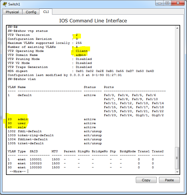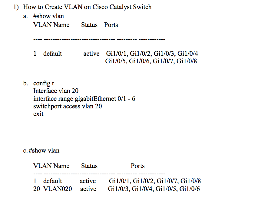

Host A has the IP address 10.0.20.11 and Host C has the IP address 10.0.30.33. To enable IP Routing, use the following command: First, enabling IP Routing and Second, applying an IP address to the VLAN. The configuration for an SVI involves two parts. Another way of looking at it is that the SVI serves as the interface on the built-in Router of the Multilayer switch, allowing traffic from one VLAN to reach the built-in Router and be routed to another VLAN as necessary. Then, for each VLAN that you want the Multilayer switch to route for, you have the option of configuring an IP address within what is known as an SVI, or a Switched Virtual Interface.Īn SVI serves as the 元 termination point for each VLAN – aka, the way in or out of each VLAN. MultilayerSwitch(config-if-range)# switchport access vlan 30 MultilayerSwitch(config)# interface range eth3/0 - 2 MultilayerSwitch(config-if-range)# switchport access vlan 20 MultilayerSwitch(config-if-range)# switchport mode access MultilayerSwitch(config)# interface range eth2/0 - 2 The Switch’s port facing the router is configured as a standard Trunk: This is in reference to the single router terminating the traffic from each VLAN. The Sub-interface feature is sometimes referred to as Router on a Stick or One-armed Router. Keep in mind, however, that the drawback with all VLANs terminating on a single Router interface is an increased risk of congestion on the link.

The only difference is with Sub-interfaces, only one Router interface is required to terminate all VLANs. The logical operation of the Sub-interface topology works exactly as the separate physical interface topology in the section before it. Hence, each router Sub-interface must also add a VLAN tag to all traffic leaving said interface. Sub-interfaces to a Router are similar to what Trunk ports are to a Switch – one link carrying traffic for multiple VLANs. That method is to create a Sub-Interface.Ī Sub-Interface allows a single Physical interface to be split up into multiple virtual sub-interfaces, each of which terminate their own VLAN. Instead, there exists a way for multiple VLANs to terminate on a single router interface. If there were five VLANs on the switch, then we would need five switchports and five router ports to enable routing between all five VLANs The previously described method is functional, but scales poorly.
#How to create a vlan on a cisco switch mac
The only difference is since there is only one physical switch, there will only be one MAC address table – each entry includes the mapping of switchport to MAC address, as well as the VLAN ID number that port belongs to.Įach switch port in this diagram is configured as an Access port, we can use the range command to configure multiple ports as once:Ĭapability Codes: R - Router, S - Switch, I - IGMP, B - Source Route Bridgeĭevice ID Local Intrfce Holdtme Capability Platform Port ID In fact, the process of a packet moving from Host A to Host D in this topology will work exactly as it does in this video. The Router operates like normal when routing packets between two networks. The Router doesn’t know that it has two connections to the same switch - nor does it need to. The simplest way to enable routing between the two VLANs to simply connect an additional port from each VLAN into a Router. The remainder of this article will explore these three options and their configuration.

Router with a Sub-Interface in each VLAN.Router with a Separate Physical Interface in each VLAN.There are three options available in order to enable routing between the VLANs: In the same way, a Router is what we will need in order for hosts in different VLANs to communicate with one another. If you’ve read the Packet Traveling series, then you know that the device which facilitates communication between networks is a Router.Ī router will perform the routing function necessary for two hosts on different networks to speak to one another. However, if Host A is trying to speak to Host C, we will need to use another device – one whose purpose is to facilitate communication between networks. This works great for Host A trying to speak to Host B. The purpose of a Switch is to facilitate communication within networks. Each VLAN will typically correspond to its own IP Network. Since Host A and Host C are in different VLANs, it is also implied that they are in different Networks. Notice since there is nothing connecting the two “virtual” switches, there is no way for Host A to speak to Host C. Despite all four hosts being connected to the same physical switch, the logical topology makes it clear that the hosts in VLAN 20 are unable to speak with the hosts in VLAN 30.


 0 kommentar(er)
